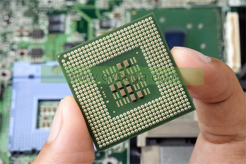
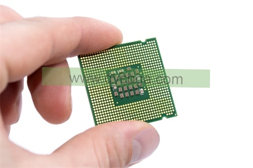
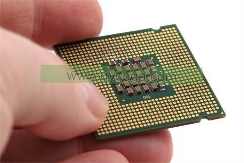
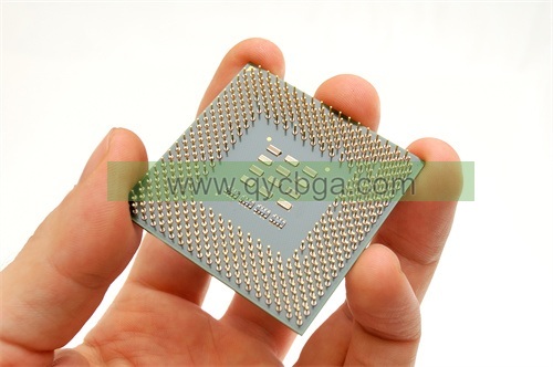
What is DIP Package Substrate?
Fabricant de substrats d’emballage DIP,DIP (Dual In-line Package) package substrate is a classic semiconductor packaging format known for its simplicity and versatility. This substrate features two parallel rows of leads extending from its body, which are inserted into corresponding holes on a circuit board for connection. DIP substrates offer ease of assembly and robust mechanical support, making them suitable for various electronic applications, from consumer electronics to industrial equipment. Typically made from materials like plastic or ceramic, DIP package substrates provide reliable electrical insulation and mechanical stability. Despite advancements in packaging technology, DIP substrates remain relevant for their cost-effectiveness and compatibility with many electronic components.
A DIP (Dual In-line Package) substrate refers to the physical material on which electronic components, such as integrated circuits (Ics) or other electronic devices, are mounted. The substrate serves as a foundation for these components and provides electrical connections between them.
In the context of DIP packages, which are commonly used for through-hole mounting of integrated circuits, the substrate typically consists of a thin, flat piece of material, often ceramic or epoxy fiberglass, with conductive traces printed or etched onto its surface. These traces provide the pathways for electrical signals to flow between the pins of the integrated circuit and other components on the circuit board.
The choice of substrate material depends on various factors such as cost, performance requirements, and manufacturing considerations. Ceramic substrates are known for their excellent thermal conductivity and reliability, making them suitable for high-performance applications. On the other hand, epoxy fiberglass substrates are more affordable and are commonly used in consumer electronics and other cost-sensitive applications.
Total, the DIP package substrate plays a crucial role in the performance and reliability of electronic circuits by providing a stable platform for mounting and interconnecting components.

Fabricant de substrats d’emballage DIP
DIP Package Substrate design Reference Guide.
A DIP package substrate design reference guide would typically provide comprehensive information and guidelines for designing the substrate used in DIP (Dual In-line Package) electronic components. Here are some key elements that such a guide might cover:
- Substrate Materials: Explanation of different substrate materials commonly used in DIP packages, such as ceramic, epoxy fiberglass, or other specialized materials. This section might include discussions on the electrical, thermique, mécanique, and cost considerations associated with each material.
- Directives de conception: Detailed guidelines for designing the substrate layout, including considerations for trace routing, via le placement, signal integrity, Distribution d’énergie, et la gestion thermique. This section might cover best practices for minimizing signal interference, reducing noise, and optimizing power delivery.
- Component Placement: Recommendations for the placement of components within the DIP package to optimize performance, minimize signal delays, and ensure proper heat dissipation. This section might include guidelines for spacing components, avoiding signal crosstalk, and maximizing electrical connectivity.
- Trace Routing: Strategies for routing electrical traces on the substrate to ensure signal integrity, adaptation d’impédance, et fiabilité. This section might cover topics such as trace width, spacing, length matching, and routing techniques for high-speed signals.
- Via Design: Guidelines for designing and placing vias (plated through-holes) on the substrate to facilitate electrical connections between different layers and components. This section might discuss via size, placement, and spacing considerations, as well as techniques for minimizing signal distortion and impedance variations.
- Gestion thermique: Recommendations for managing thermal issues within the DIP package, including heat dissipation, thermal vias, and thermal pad design. This section might cover techniques for optimizing thermal conductivity, reducing thermal resistance, and ensuring reliable operation under various temperature conditions.
- Manufacturability and Reliability: Considerations for designing the substrate to ensure manufacturability, fiabilité, et rapport coût-efficacité. This section might include guidelines for design for manufacturing (DFM), design for assembly (DFA), and design for reliability (DFR) principles.
- Études de cas et exemples: Practical examples, case studies, and real-world applications of DIP package substrate design, demonstrating how different design principles and techniques can be applied to specific scenarios.
Total, a DIP package substrate design reference guide would aim to provide engineers and designers with the knowledge and tools needed to create high-performance, reliable, and cost-effective DIP packages for a wide range of electronic applications.
What are the materials used in DIP Package Substrate?
The choice of materials for DIP (Dual In-line Package) package substrates depends on various factors such as cost, performance requirements, Besoins en matière de gestion thermique, et fabricabilité. Here are some common materials used in DIP package substrates:
- Ceramic: Ceramic substrates, often made of alumina (Al2O3) or aluminum nitride (Aln), are known for their excellent thermal conductivity, high mechanical strength, et fiabilité. Ceramic substrates are well-suited for high-performance applications where thermal management is critical, such as in power electronics and high-frequency circuits.
- Epoxy Fiberglass: Epoxy fiberglass substrates are made of a composite material consisting of a woven fiberglass fabric impregnated with epoxy resin. These substrates are cost-effective, lightweight, and offer good electrical insulation properties. Epoxy fiberglass substrates are commonly used in consumer electronics and other cost-sensitive applications.
- FR-4: FR-4 is a type of flame-retardant fiberglass composite material widely used in printed circuit boards (PCBs) and DIP package substrates. It consists of woven fiberglass fabric impregnated with epoxy resin and reinforced with a flame-retardant additive. FR-4 substrates offer good mechanical strength, electrical insulation, et rapport coût-efficacité, making them suitable for a wide range of applications.
- Polyimide: Polyimide substrates, also known as Kapton, are flexible, high-temperature-resistant materials commonly used in flexible circuitry and DIP packages where flexibility is required. Polyimide substrates offer excellent thermal stability, chemical resistance, and flexibility, making them suitable for applications in harsh environments or where space constraints exist.
- Metal-Core PCB (MCPCB): Metal-core PCB substrates consist of a thermally conductive metal core (comme l’aluminium ou le cuivre) sandwiched between layers of dielectric material (such as epoxy fiberglass or polyimide). These substrates offer superior thermal management capabilities, making them ideal for high-power LED lighting applications and other heat-sensitive electronic devices.
- Copper: Copper substrates, typically used in metal-core PCBs, offer high thermal conductivity and can efficiently dissipate heat generated by electronic components. Copper substrates are often used in high-power applications where thermal management is critical.
The choice of substrate material depends on the specific requirements of the application, including thermal performance, Propriétés électriques, résistance mécanique, flexibility, and cost considerations. Designers must carefully evaluate these factors to select the most suitable material for their DIP package substrate.
How is DIP Package Substrate manufactured?
The manufacturing process for DIP (Dual In-line Package) package substrates typically involves several steps to create the foundation upon which electronic components will be mounted. Here’s a general overview of the manufacturing process:
- Substrate Preparation: The manufacturing process begins with the preparation of the substrate material. En fonction de la matière choisie (e.g., céramique, epoxy fiberglass, FR-4), the substrate may be in the form of sheets or panels.
- Substrate Cleaning: The substrate material undergoes cleaning to remove any contaminants, oils, or residues that could interfere with subsequent processing steps. Cleaning is typically done using solvents, detergents, or other cleaning agents.
- Circuit Pattern Generation: The circuit pattern, including conductive traces and component pads, is generated on the substrate material using various techniques such as screen printing, photolithography, or chemical etching. For example, in the case of copper traces on epoxy fiberglass or FR-4 substrates, a layer of copper may be deposited onto the substrate using a process such as electroplating, followed by the removal of excess copper through etching to create the desired circuit pattern.
- Dielectric Layer Deposition: If necessary, additional dielectric layers may be deposited onto the substrate to insulate the conductive traces and provide mechanical support. This step helps to prevent short circuits and ensures proper electrical isolation between circuit layers.
- Via Formation: Vias (plated through-holes) are created in the substrate to facilitate electrical connections between different layers of the circuit. Vias may be drilled or punched into the substrate, and then plated with conductive material such as copper to establish electrical continuity between layers.
- Finition de surface: The substrate surface may undergo surface finishing processes to improve solderability and protect against oxidation. Common surface finishes include hot air solder leveling (HASL), electroless nickel immersion gold (ENIG), et l’argent d’immersion.
- Component Mounting: Once the substrate is prepared, electronic components such as integrated circuits (Ics), resistors, capacitors, and diodes are mounted onto the substrate using automated pick-and-place machines or manual assembly techniques.
- Soldering: The components are soldered onto the substrate to establish electrical connections between the component leads or terminals and the conductive traces on the substrate. Soldering may be performed using reflow soldering, wave soldering, or hand soldering techniques, depending on the specific requirements of the assembly process.
- Essais et inspections: After assembly, the DIP package substrates undergo testing and inspection to ensure that all components are properly mounted, and electrical connections are functioning as intended. Various testing methods such as continuity testing, functional testing, and automated optical inspection (AOI) may be employed to verify the quality and reliability of the substrates.
- Emballage et expédition: Once testing and inspection are complete, the DIP package substrates are packaged according to customer specifications and shipped to their destination for further assembly or integration into electronic devices.
Total, the manufacturing process for DIP package substrates involves a series of precise and controlled steps to create reliable and functional foundations for electronic components. Each step in the process plays a crucial role in ensuring the quality, performance, and reliability of the finished substrates.
The Application area of DIP Package Substrate
DIP (Dual In-line Package) package substrates find applications across various industries and electronic devices due to their versatility, fiabilité, and ease of use. Some common application areas of DIP package substrates include:
- Électronique grand public: DIP package substrates are widely used in consumer electronics such as TVs, audio equipment, home appliances, and gaming consoles. They can be found in circuit boards for power supplies, audio amplifiers, signal processing units, and control systems.
- Industrial Electronics: Industrial equipment and machinery often rely on DIP package substrates for control systems, motor drives, sensors, and monitoring devices. These substrates provide the necessary electrical connections and mechanical support for reliable operation in harsh industrial environments.
- Télécommunication: DIP package substrates are used in telecommunications equipment such as routers, Commutateurs, modems, and base stations. They play a crucial role in signal processing, data transmission, and network connectivity within telecommunications networks.
- Électronique automobile: In the automotive industry, DIP package substrates are employed in vehicle control systems, engine management units, systèmes d’infodivertissement, and safety systems. They help facilitate communication between various vehicle components and ensure reliable operation under challenging conditions.
- Dispositifs médicaux: DIP package substrates are utilized in medical devices and equipment such as patient monitoring systems, diagnostic instruments, Appareils d’imagerie, and surgical equipment. They provide the necessary connectivity and functionality for precise data acquisition, processing, and control in medical applications.
- Aérospatiale et défense: Aerospace and defense applications require high-reliability electronic components, making DIP package substrates suitable for avionics systems, navigation equipment, systèmes radar, and communication devices used in aircraft, spacecraft, and defense systems.
- Power Electronics: DIP package substrates play a crucial role in power electronics applications such as power supplies, motor drives, inverters, and renewable energy systems. They enable efficient power distribution, voltage regulation, and energy conversion in various power management applications.
- LED Lighting: DIP package substrates are commonly used in LED lighting applications for residential, commercial, and industrial lighting fixtures. They provide the structural support and electrical connectivity needed for LED driver circuits, thermal management systems, and control interfaces.
Total, DIP package substrates are versatile components that serve as the foundation for a wide range of electronic devices and systems across industries, contributing to their functionality, fiabilité, and performance.
What are the advantages of DIP Package Substrate?
DIP (Dual In-line Package) package substrates offer several advantages that make them a popular choice for electronic component packaging and assembly. Here are some of the key advantages:
- Mechanical Stability: DIP packages provide mechanical stability and protection for electronic components due to their rigid structure and encapsulation. This helps prevent damage from mechanical shocks, vibrations, and environmental stresses.
- Ease of Assembly: DIP packages are relatively easy to assemble using automated pick-and-place machines or manual soldering techniques. The through-hole mounting style of DIP packages allows for secure attachment of components to the substrate, making assembly straightforward and efficient.
- Versatility: DIP packages are available in a variety of configurations, including single-inline, dual-inline, and quad-inline packages, making them suitable for a wide range of electronic components and applications. They can accommodate different numbers of pins and pin spacings to meet specific design requirements.
- Interchangeability: DIP packages are often designed with standardized pin layouts and dimensions, allowing for interchangeability of components across different manufacturers and product lines. This interchangeability simplifies inventory management, repair, and replacement of electronic components.
- Thermal Performance: DIP packages offer good thermal performance, especially when mounted on substrates with high thermal conductivity such as ceramic or metal-core PCBs. This helps dissipate heat generated by electronic components, reducing the risk of thermal damage and improving overall reliability.
- Electromagnetic Shielding: DIP packages can provide electromagnetic shielding for sensitive electronic components, protecting them from electromagnetic interference (EMI) and radiofrequency interference (RFI). This shielding helps ensure proper functioning of electronic circuits in noisy electromagnetic environments.
- Cost-Effectiveness: DIP packages are often cost-effective compared to other packaging options such as surface-mount technology (SMT) packages or ball grid arrays (BGAs). Their simple design, ease of assembly, and compatibility with standard manufacturing processes contribute to lower production costs.
- Accessibility for Testing and Troubleshooting: DIP packages facilitate easy access to component leads or pins, making them convenient for testing, troubleshooting, and repair of electronic circuits. This accessibility allows technicians to probe individual pins or perform visual inspections without disassembling the entire package.
Total, DIP package substrates offer a combination of mechanical stability, ease of assembly, versatility, performances thermiques, electromagnetic shielding, cost-effectiveness, and accessibility, making them well-suited for a wide range of electronic applications across industries.
How Much Does DIP Package Substrate Cost?
The cost of DIP (Dual In-line Package) package substrates can vary significantly depending on several factors, including the substrate material, taille, complexité, quantity, and manufacturing processes involved. Here are some factors that can influence the cost:
- Matériau du substrat: Different substrate materials, such as ceramic, epoxy fiberglass, FR-4, or metal-core PCBs, have different costs associated with their production. Ceramic substrates, par exemple, tend to be more expensive due to their high thermal conductivity and reliability properties.
- Taille et complexité: The size and complexity of the DIP package substrate, y compris le nombre de couches, trace density, and via count, can impact the manufacturing cost. Larger and more complex substrates require more materials and processing steps, leading to higher costs.
- Procédés de fabrication: The manufacturing processes involved in producing the substrate, such as circuit pattern generation, via formation, finition de surface, component mounting, soldering, testing, and inspection, can contribute to the overall cost. More sophisticated processes may incur higher manufacturing costs.
- Quantity: Economies of scale can affect the cost of DIP package substrates, with larger production quantities generally resulting in lower per-unit costs. Bulk ordering or long-term contracts with suppliers may lead to volume discounts and reduced costs per unit.
- Customization: Customized features or specifications, such as special surface finishes, unique circuit layouts, or specific substrate materials, may increase the cost of DIP package substrates compared to standard off-the-shelf options.
- Supplier and Location: The choice of supplier and their location can impact the cost of DIP package substrates. Suppliers with advanced manufacturing capabilities or lower labor and overhead costs may offer competitive pricing.
- Conditions du marché: Market conditions, including fluctuations in raw material prices, currency exchange rates, and supply chain disruptions, can affect the overall cost of DIP package substrates.
Due to these factors, it’s challenging to provide a precise cost estimate for DIP package substrates without specific details about the requirements and manufacturing parameters. Toutefois, as a rough estimate, the cost of DIP package substrates can range from a few cents to several dollars per unit, depending on the aforementioned factors. Large-scale production runs typically result in lower per-unit costs, while smaller batches or customized substrates may incur higher costs.
FAQs about DIP Package Substrate
What is a DIP package substrate?
A DIP package substrate is the physical material on which electronic components, such as integrated circuits (Ics), are mounted. It provides the foundation for the components and facilitates electrical connections between them.
What materials are used in DIP package substrates?
Common materials used in DIP package substrates include ceramic, epoxy fiberglass, FR-4, polyimide, metal-core PCBs, and copper. The choice of material depends on factors such as cost, performance requirements, and manufacturing considerations.
How are DIP package substrates manufactured?
The manufacturing process for DIP package substrates typically involves substrate preparation, circuit pattern generation, dielectric layer deposition, via formation, surface finish, component mounting, soldering, testing, and inspection.
What are the advantages of DIP package substrates?
Some advantages of DIP package substrates include mechanical stability, ease of assembly, versatility, performances thermiques, electromagnetic shielding, cost-effectiveness, and accessibility for testing and troubleshooting.
What are the application areas of DIP package substrates?
DIP package substrates find applications across various industries, y compris l’électronique grand public, industrial electronics, télécommunication, Électronique automobile, Dispositifs médicaux, Aérospatiale et défense, power electronics, and LED lighting.
How much does a DIP package substrate cost?
The cost of DIP package substrates can vary depending on factors such as substrate material, taille, complexité, quantity, Procédés de fabrication, customization, supplier, et les conditions du marché. Costs can range from a few cents to several dollars per unit.
What are some considerations for designing DIP package substrates?
Design considerations for DIP package substrates include substrate material selection, trace routing, via le placement, component placement, Gestion thermique, manufacturability, et fiabilité.
How do DIP package substrates differ from other package types?
DIP package substrates differ from other package types, such as surface-mount technology (SMT) packages and ball grid arrays (BGAs), in terms of their mounting style, electrical connections, and mechanical characteristics.
 Fabricant de substrats d’emballage FCBGA


